1969 Dodge Dart Midplate

Product


1/4" T6 6061 mid-plate for a 69 Dodge Dart using a Reid transmission.

Scope: My neighbor has a 1969 Dodge Dart and a physical blue print of the transmission layout. Unfortunaly none of the dimensions were on the print, which was extremely important for alignment of this 900HP+ rotating assembly…. so we had to get crafty.

  • First we took a high resolution photo of the print with a scale next to it for size
  • Then imported the image into the a CAD system to trace and place the geometry, including the one inch march on the scale
  • After the geometry was done, I scaled the 2D wireframe using the hashes off the ruler to indicate a 1 inch scale.
  • Extruded the geometry and produced the 3D model THAT ACTUALLY FIT!!

Designed using Fusion 360


Designed Part

Machined on Haas TM1


Finished Machined Part

Resting in place to evaluate clearance


Clearance Check

Chrysler Mold Modification

Product


Chrysler B Pillar Door Tool Modification

Scope: This particular mold produced a fiberglass tool that held the door ajar for a painting robot on a chrysler vehicle. The two inner slots slid over the B pillar frame and the extruding slot held the door. The customer wanted the mold modified to slightly move the door slot outward as well as adding a handle to grab the tool from the door.

  • Looking at the mold, the bottom right side needs to be machined differently. Working with hbkenterprise, we came up with a proposal to machine out a rectangular area and insert an aluminum block with the proper geometry. This block would be bolted in from the front side as top allow easier machining in the future and the ability to switch out inserts.

Designed Part

  • First, the pocket was machined out, with a .5" endmill, to accept the insert

Designed Part

  • Then Drilled and tapped to accept 1/4-20 socket head cap screws

Designed Part

  • Machined the insert, from a block of aluminum, to the new geometry specifications.

Designed Part

  • Then bolt it together to produce the finished product.

Designed Part

Chrysler Mold Designed and Machined

Product


Chrysler B Pillar Mold

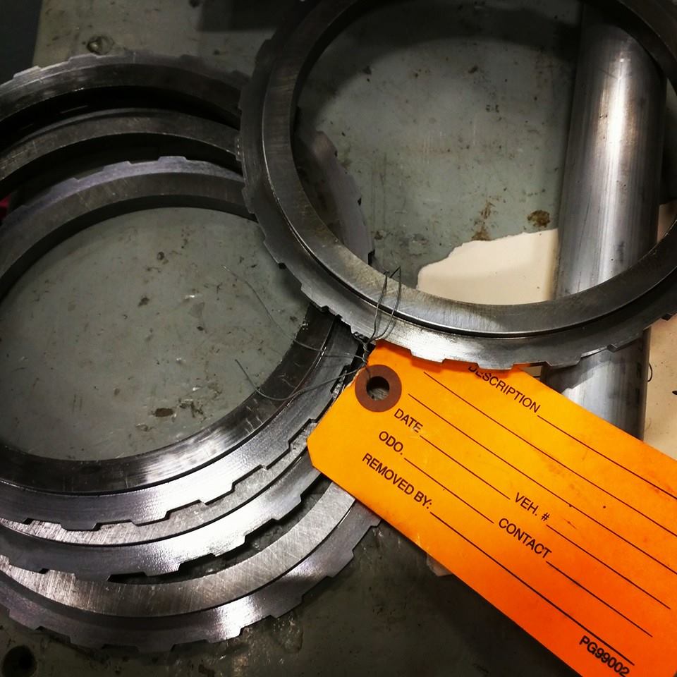
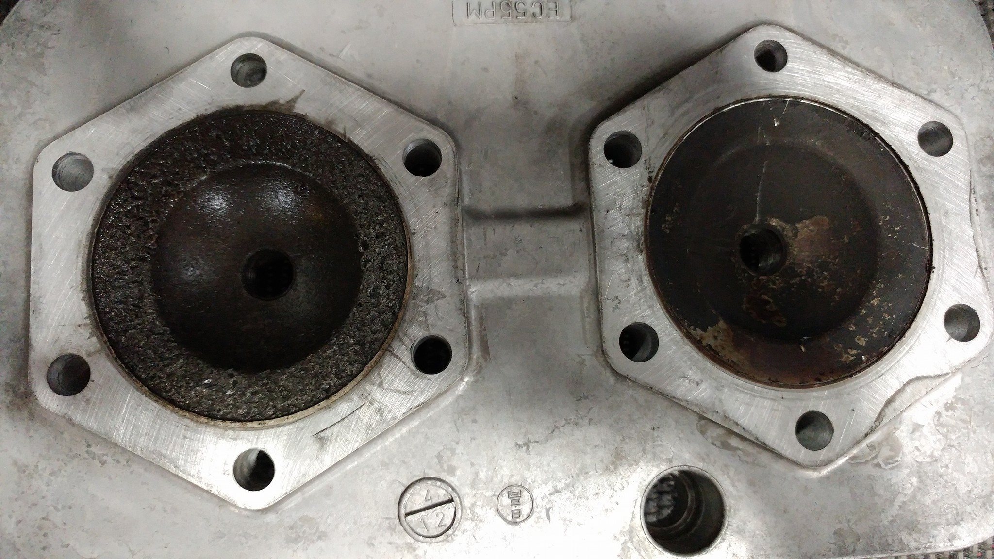
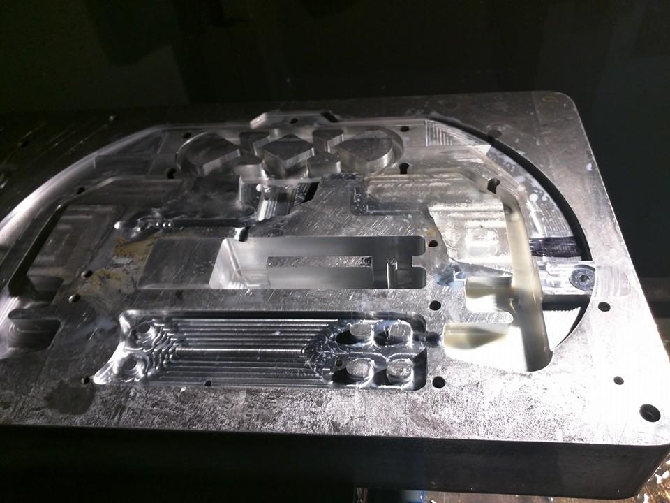
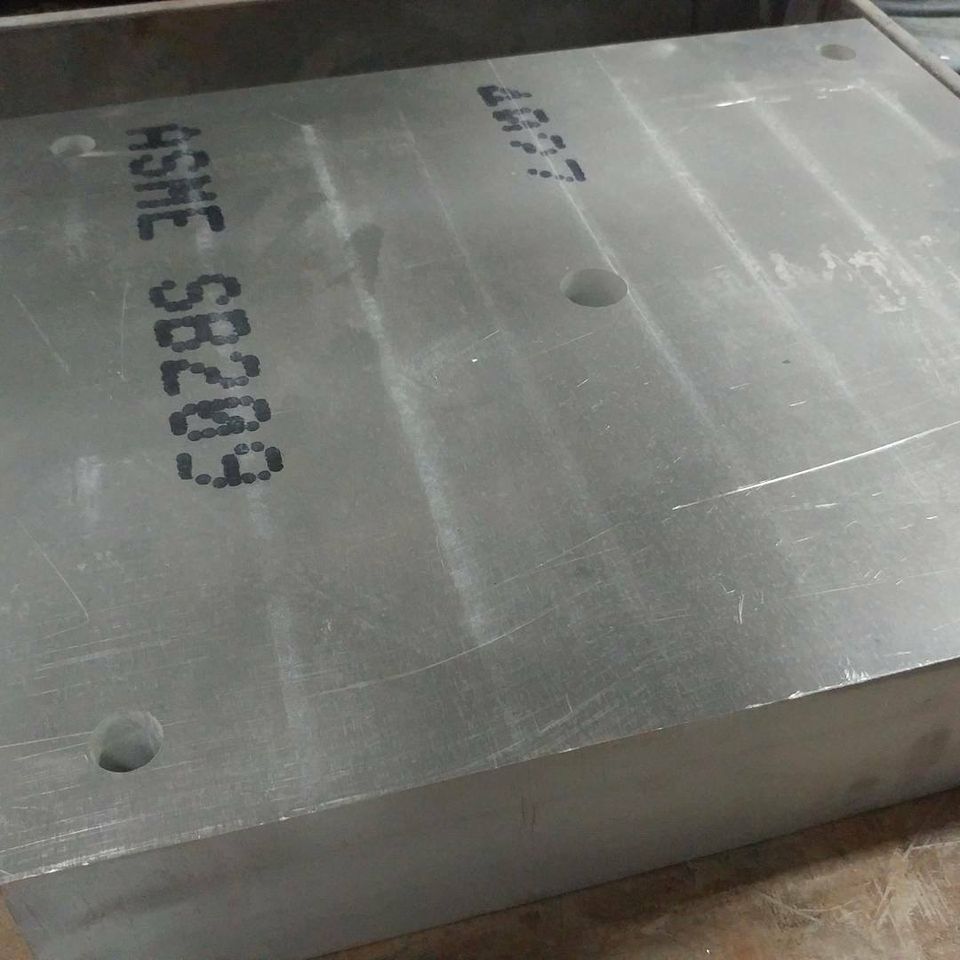
Scope: The Customer had been modifying a legacy insert to the point that there was not much left to work with. The mold was made by a previous machine shop and we modified it on several occasions, per the customer, in efforts to save the mold and save money. Problem was that we were running into machining through empty areas and drilling through unknown pockets in the material. These conditions would present new issues and additional work during the machining process such as drilling drift issues because of the irregular surfaces buried in the mold and milling through hidden bolts. This was costing me a lot of time and resources beyond the original scope of work. To my luck, the final straw came when an injection house bent the mold and it was no longer usable. As you can see from the photo below, there was not much left of the structure.

Too Much

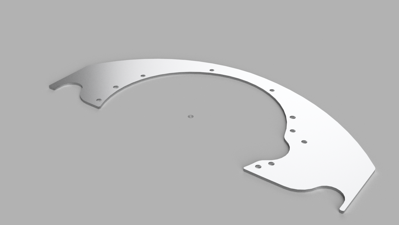
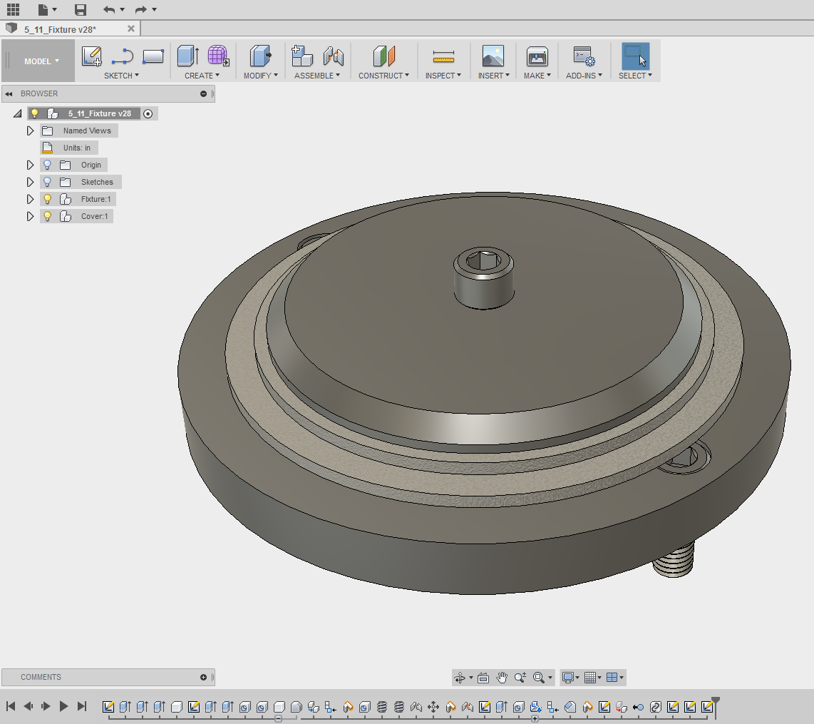
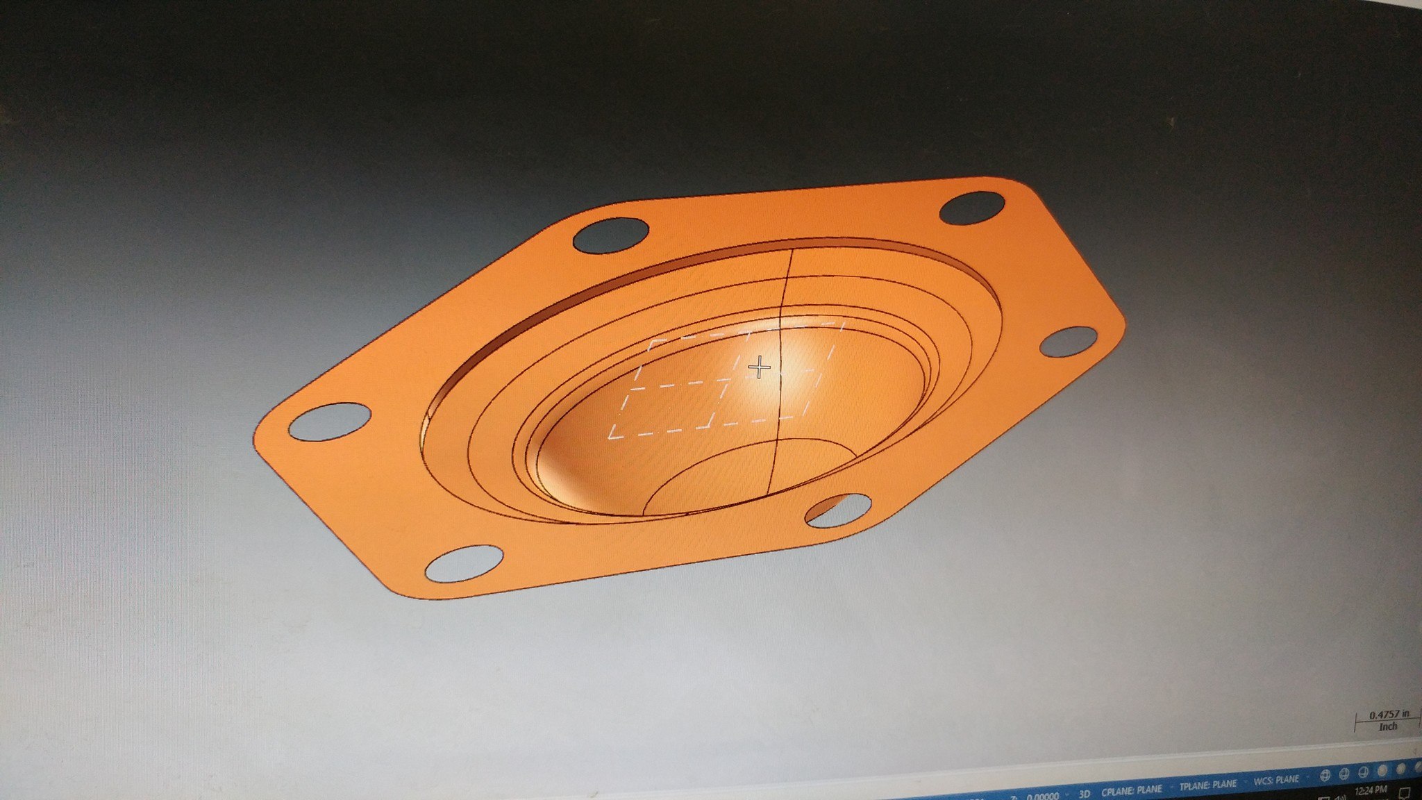
The customer asked HBK Enterprise to design them a new mold using the several attributes of the attributes of the old part with some modernization. The owner of HBK and I were good friends and business partners so he designed the mold while working with me to accommodate machining tools that I had available. This made the manufacturing process substantially easier as I was limited by the machine tool.

Designed Mold

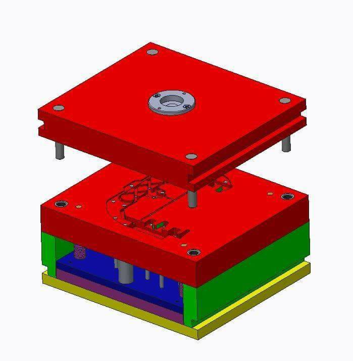
HBK Enterprise ordered the material with some pre-selected geometry as to aid in the manufacturing process.

Cavity Blank

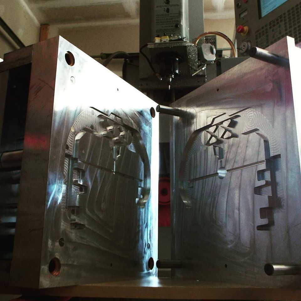
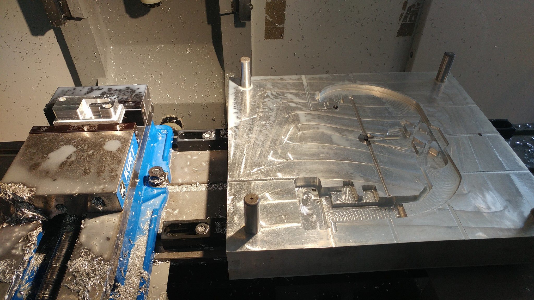
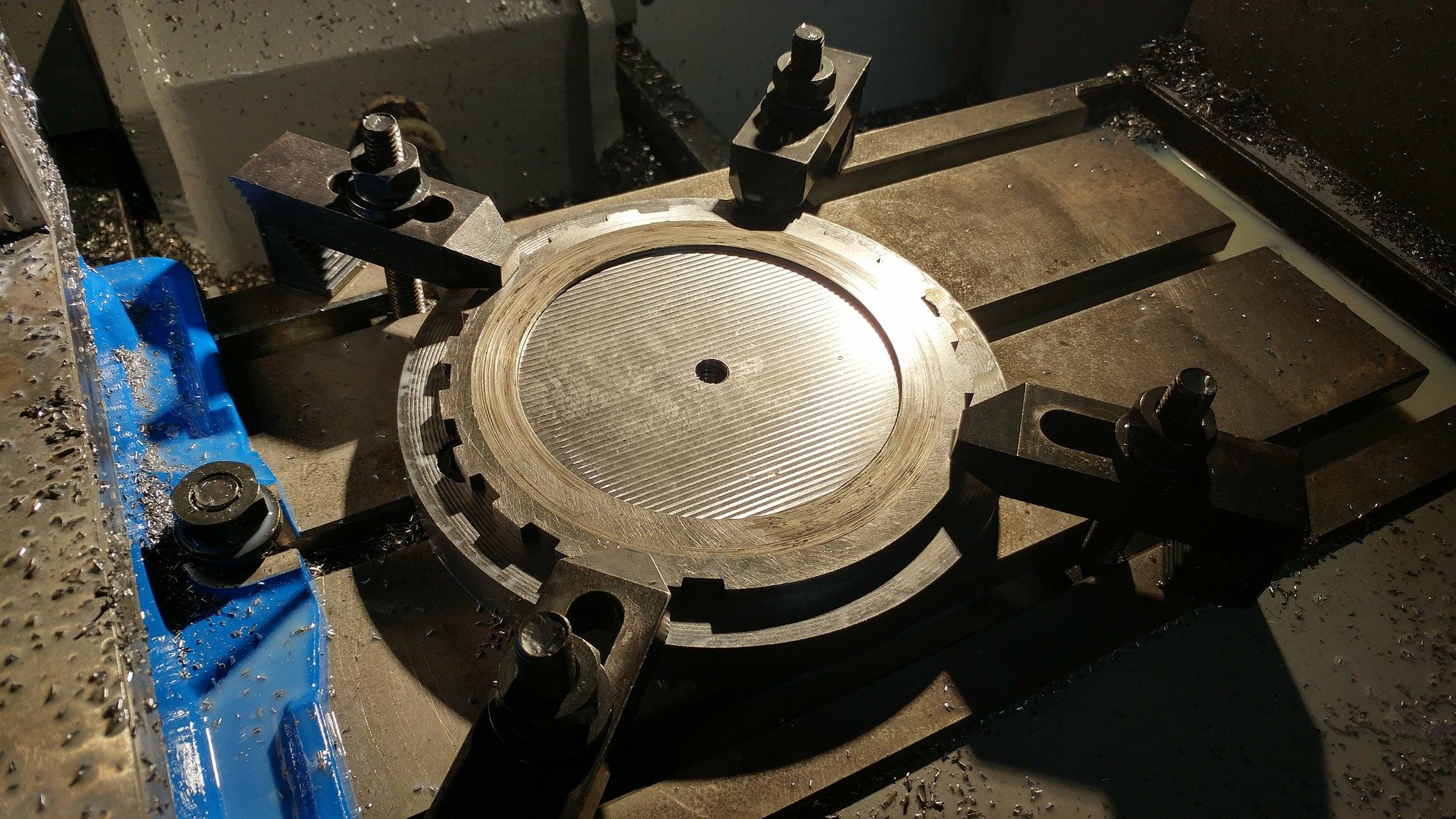
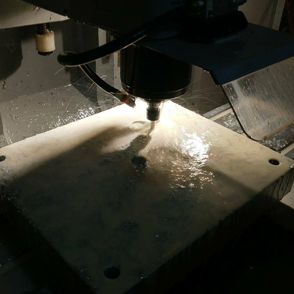
As you can see in this photo, the mold is 2 times larger than my machining table and I had to use the pre-machined geometries to pick up on. Each side had 2 setups, milling from the center hole down, then from the center hole up.

Mold on Table

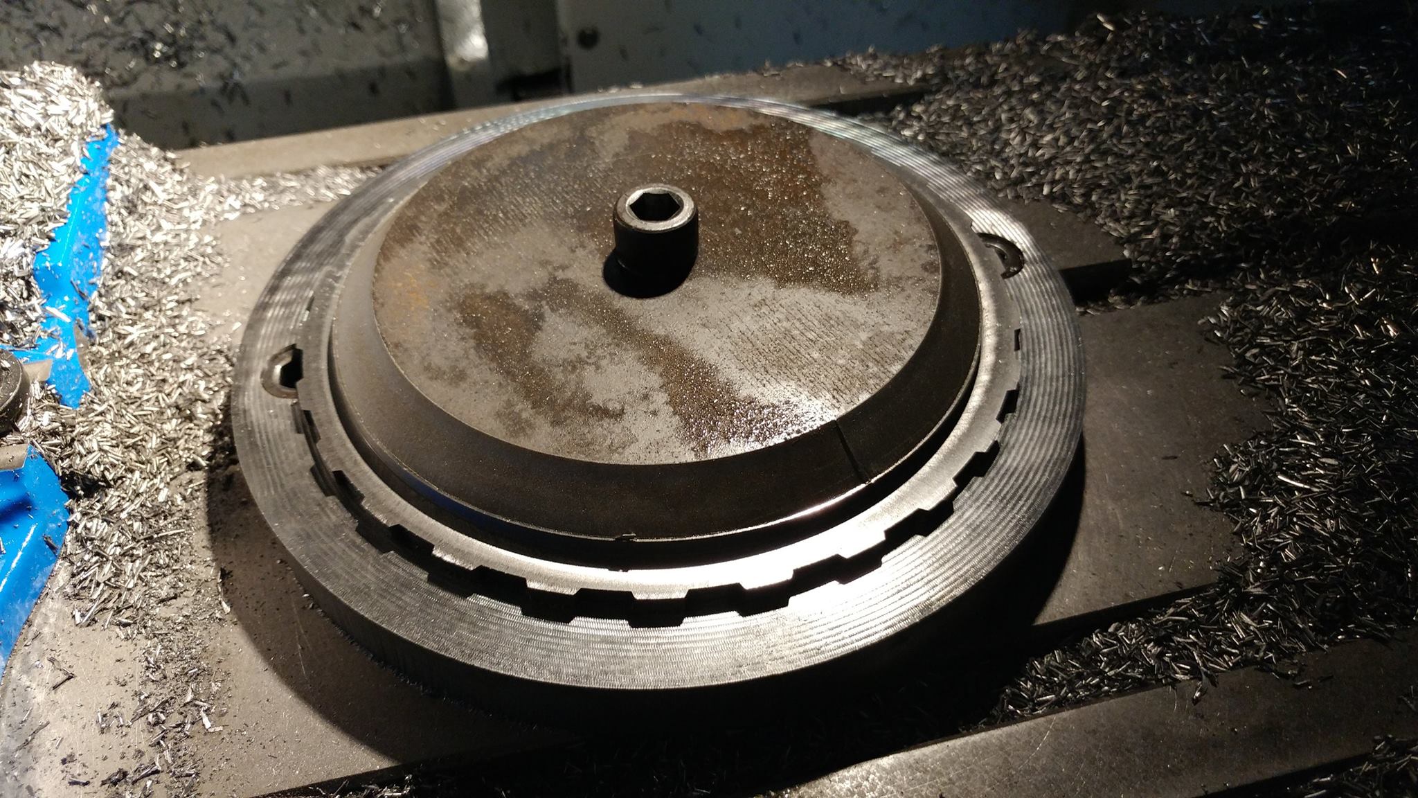
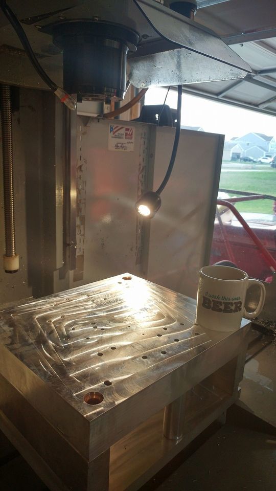
Here is the Large base fully assembled on the table. I machined all the lower pieces then assembled the mold and machined the top flat. This was to done to ensure the top of the mold was parallel to the bottom of the mold, regardless of the tolerances that could be in between (ie. Bottom plate and the legs).

Flat top

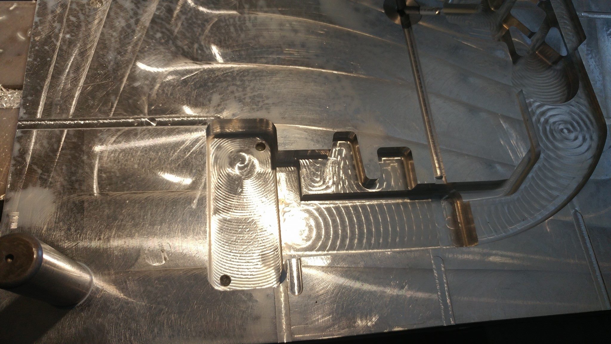
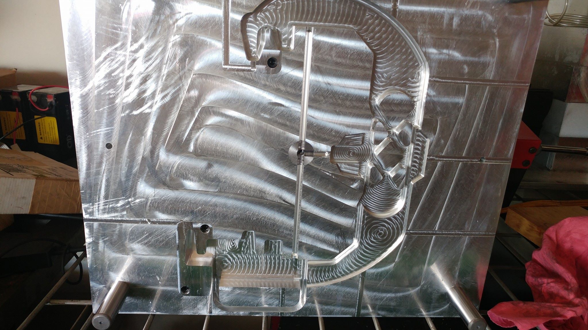
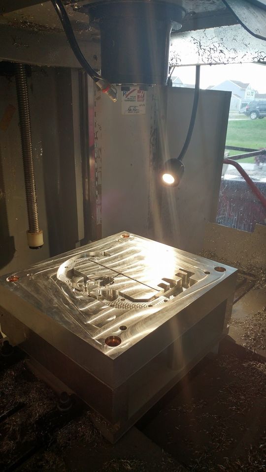
Here the final geometry is machined into this half of the mold along with the pushpin holes and runners. The ballscrew and liner guides of the machine are exposed because I had to remove the way cover to accommodate the the size of the mold. Without modifying the machine, the material would have destroyed to protective shield.

Machined our

The complete core and cavity took about a week to finish. I worked on weekends and after my normal job everyday to finish this project in the 14 day timeframe from the customer. That is right… 14 days desingned and machined.

Finished Mold

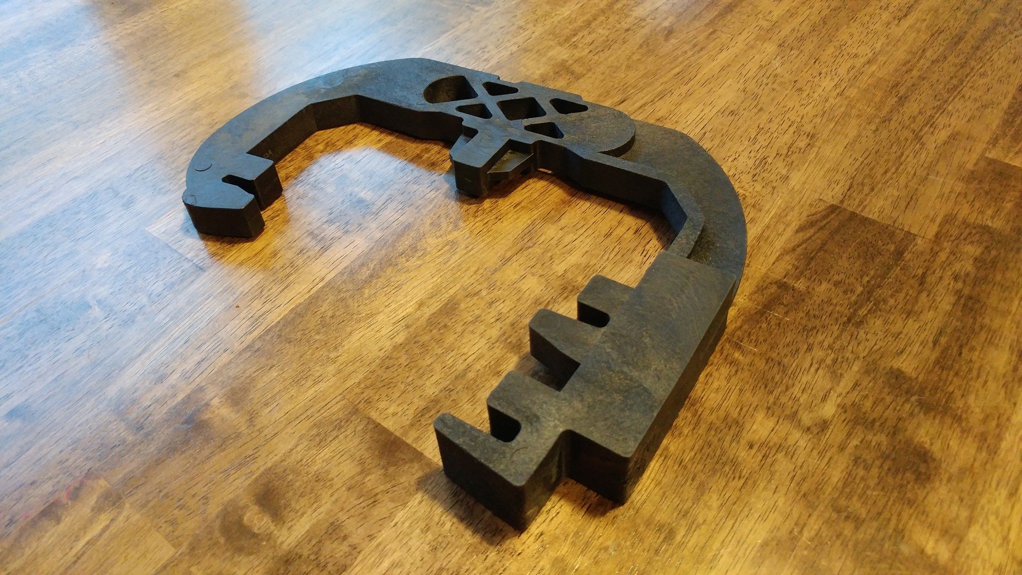
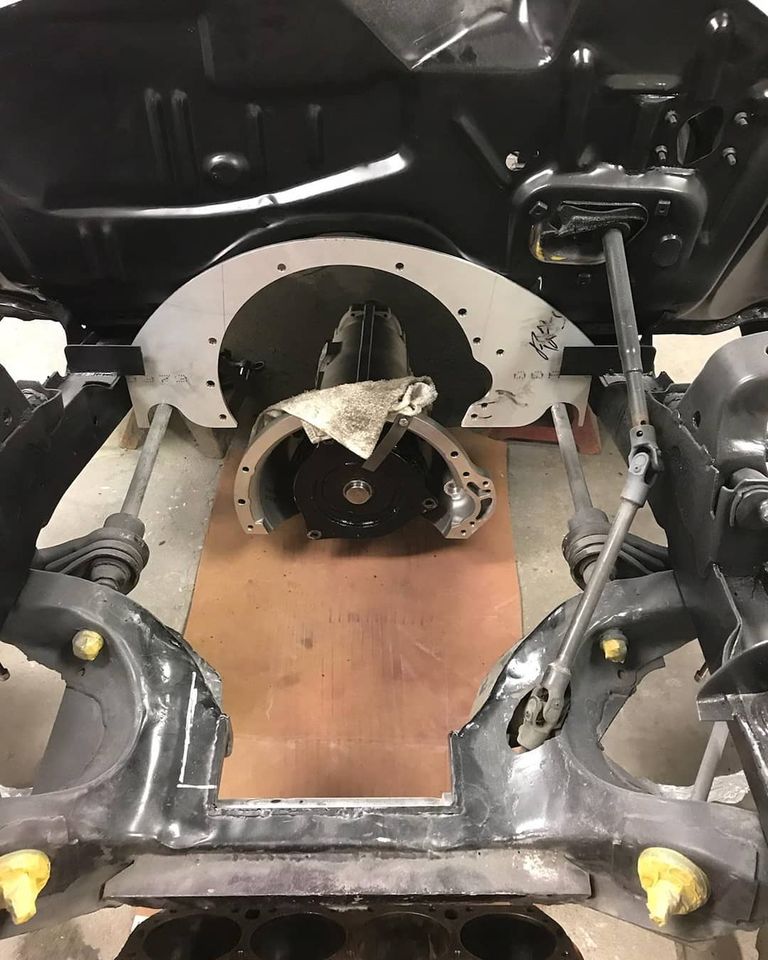
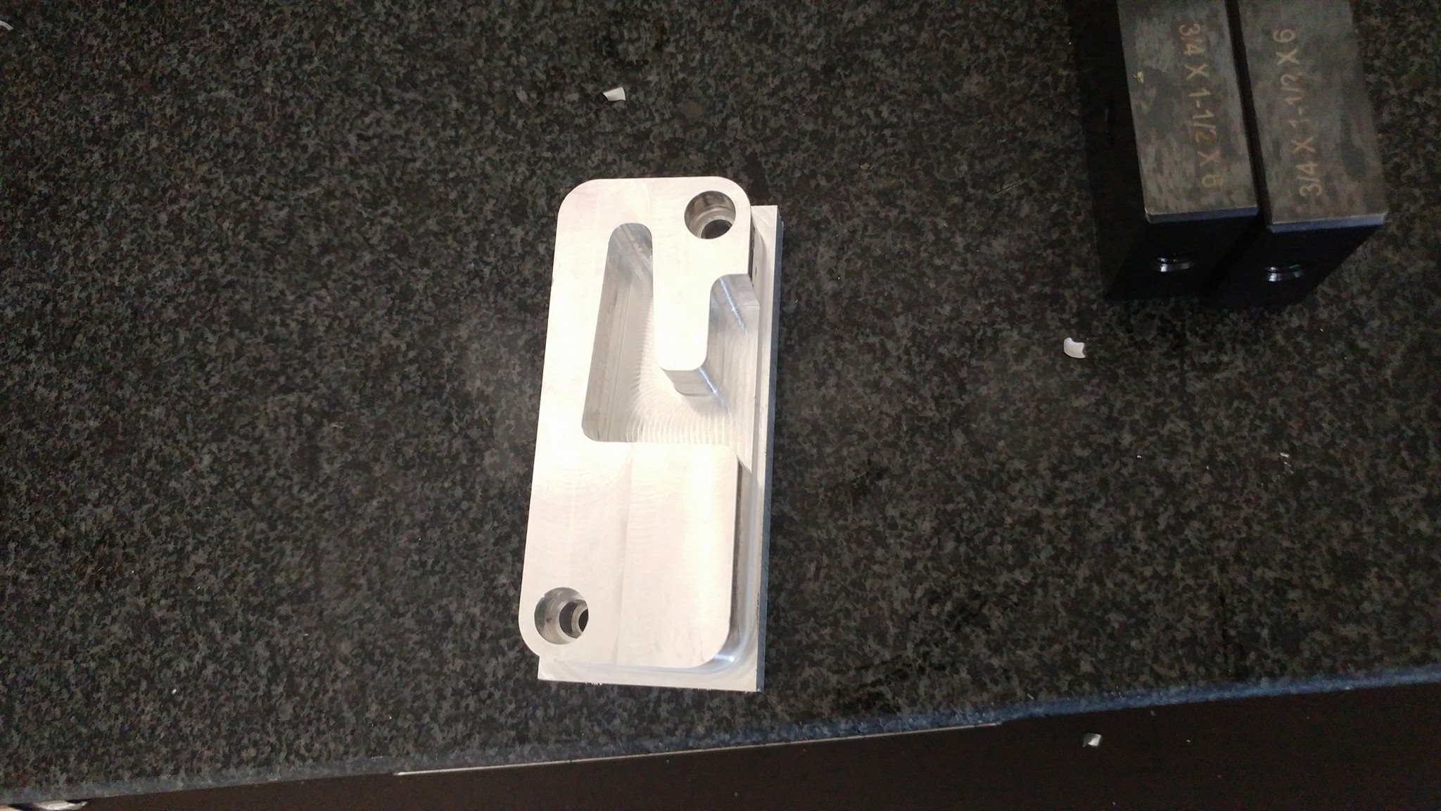
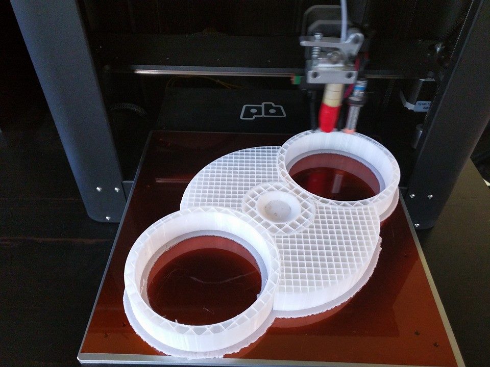
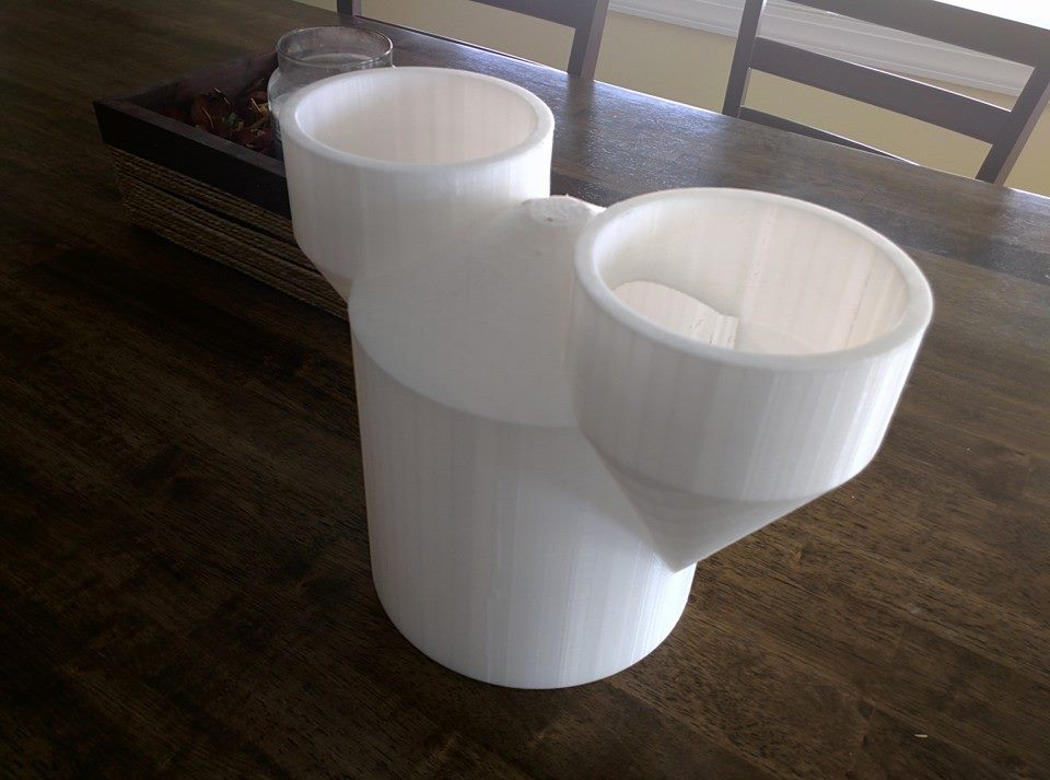
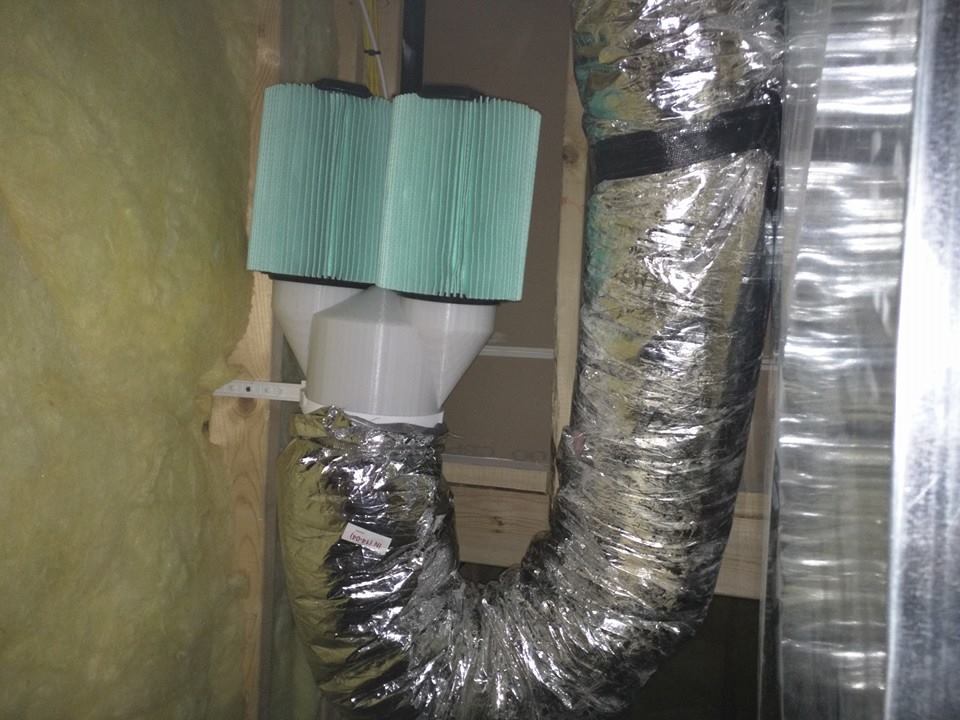
Below is and example of the finished part

B Pillar tool

Backing Plates

Product


Backing Plate for High Performance Transmissions

Barry Papke (Bear) from Bear’s Performance Transmission contacted me about machining some backing plate for his high performance transmissions. Apparently there wasnt a machine shop for miles that would touch such a small quantity (5-15) without an astroniomical price tag. From our lengthy conversation, here is what I gathered.

  • The backing plates were to machined down a little bit to accomodate a few more clutch plates in the transmission (steel and clutch material).
  • These plates were used in a lot of the locals transmissions, so I would get a personal shout out with each rebuild.
  • His biggest customer was Dan Perkins who owned Perkins tile and Marble. This guy also was the pinnacle of off roading in our area and was followed and adored by thousands of people… So that would be a huge win for free publicity
  • The part would be at max 20 plates at a time but sometimes less than that. On the bright side, there was only a few variants.
  • Witha verbal agreement and a hand shake, I was going to invest in a few fixtures and machine these parts as needed, with a fixed price for each. Luckily this customer was good on his lead times and was easy to work with
  1. First things first, I had to reverse engineer the part, design it, then design a fixture for it. While looking for affordable CAD/CAM packages online, I came accross Fusion 360 as a “Free to Use” software packages for small businesses starting up. Seemed like a perfect oppourtunity to learn a new software package and save a ton of money at the same time

  2. I designed the fixture to work with a few different parts and be interchangeable with how I have to machine the items. From the image below, you can see that this part is almost a solid ring sandwiched between a lid and the base. The light brown area is the finished replica with the step machined out of it.

This is a low profile, bolt through, design with 1/2"-13 socket head cap screws to allow for the largest contact area, low fixture torque, and exterior clamping.

Fixture CAD

Backing ring with outer diameter machined

Fixture 1

Switched Configuration with Backing ring and inner diameter machined

Fixture 2

Completed Parts

Backing Rings

Snowmobile

Product


Snowmobile Aluminum Head Remachine

Scope: Customer came through with a snowmoblie head that seemed to have taken a lot of damage. I believe a part of the spark plug fell into the combustion chamber while it was running. Apparently parts for this older model were hard to find and costly when you could find them. The Customer and I agreed that modifying the head could cause clearance or combustion issue, but in the end, the customer said he had nothing to lose if we tried.

  • Looking at the head, I decided whatever I did to one side had to be done to the other. I was going to rough machine the surface down .01" at a time until it was all undamaged material.

Designed Part

  • Getting started, I needed good a good part to measure against so that I could reverse engineer the geometry to use for machining. I decided to clean up the undamaged side and use a portable CMM to create a 2D flat pattern by measuring a continuous point line projected against a plane. This geometry could then be revolved into a surface that was trimmed to the flat geometries I measured afterward.

Designed Part

  • With the knew geometry, I machined each profile, individually, down to the same depth.

Designed Part

  • The finished product worked and the snowmobile still runs to this day!

Fresh Air Manifold

Product


Fresh Air Return Filter

  • Scope: After moving into a newly build house, I noticed a large insulated vent hanging from the ceiling. After tracking it back through the floor joist and saw that it terminated through the wall, it was apparent that this was the fresh air makeup vent for the entire house. For those of you who do not know much about modern HVAC, fresh air makeup vents are used to not only bring in fresh air, which your house needs, but to also prevent fires from occurring with combustion based appliances. A good example would be a gas water heater and a dryer. Both appliances have induction motors that force air out of the house…but that air has to come from somewhere. ie. When you turn on your dryer, it sucks air from inside the house, through a heat exchanger, and then outside, same with the hot water tank. Now, without the fresh air make up, the appliances fight against each other like two people sucking on the same straw from either end. The appliance with the stronger induction fan will pull the flame backwards from the other unit, also dubbed “roll-out”. So if the dryer has a stronger fan, then the flames going upward and out of the hot water tank are now being sucked backwards and you could potentially see the flame coming out of the bottom of the hot water tank. Now this is an extreme condition where the house is truly air tight and several safety features of your modern appliances fail to work….but it can happen.

You can see the black, insulated, makeup vent hanging from the ceiling to the floor. (Not my house, but they are all pretty much the same)

Designed Part

  • My problem fruitioned when I noticed a lot of dirt and bugs in my basement…plus in the wintertime, the amount of cold air coming in was insane. Knowing that I could not cover the vent, I initially dropped the end into a 5 gallon bucket in hopes of slowing down the convectional currents. Then I tried to tape some fabric over the end to keep the bugs and dirt out but that was a failure because of the amount of bugs and that loaded up into it eventually clogged the cloth. My final attempt was going to have to be engineered as off-the-shelf solutions were pretty expensive and not exactly what I wanted.

Designed Part

  • My “at home” solution was to 3D print a custom manifold that used hose clamps to attach itself to the insulated vent. The vent would house 2 common style filters that had the lowest risk of obsolescense, cheap, and effective.

Designed Part

  • I ended up using 2 new HEPA filters from a Rigid shop vac. Come to find out, several Rigid models and other manufacturers use the same style filter that they rebrand under their own name. The fliters friction slipped onto the end of the manifold and I mounted it upright to slow down convectional currents.

Designed Part